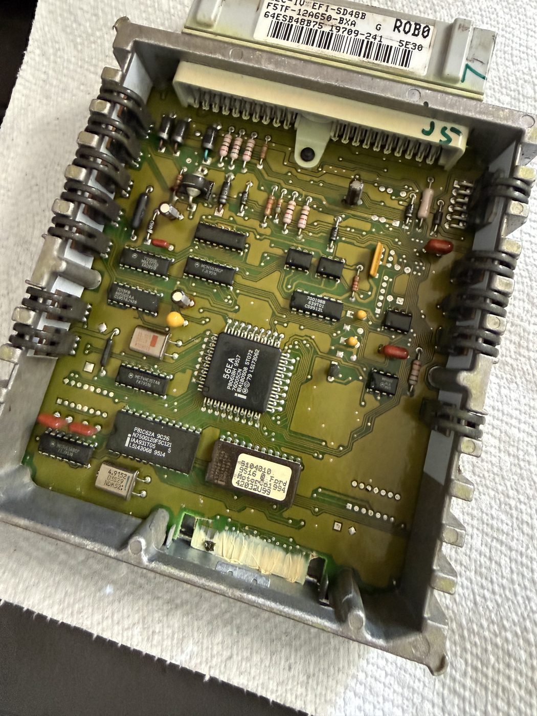
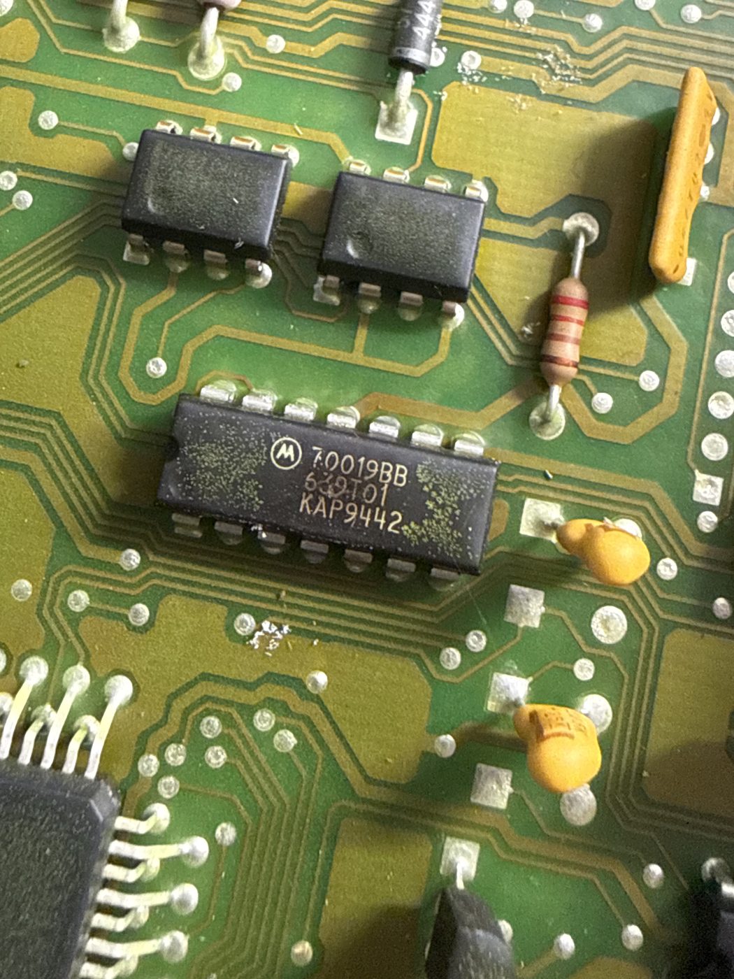
The brain of my 1995 Bronco is a Ford EEC-IV processor, part number F5TF-12A650, the engine computer for the 5.8L 351 Windsor. These units are bulletproof in most respects, but they all share one ticking time bomb: the little electrolytic capacitors on the board. Three decades of heat cycles later, they leak, and the electrolyte that escapes is corrosive enough to eat the copper traces right off the board. So before the truck leaves me stranded, I pulled the computer apart to deal with it on my terms.
Why these fail: the electrolytic capacitors Ford used were good for maybe 15 to 20 years. Past that, age and underhood heat dry them out and they begin to weep. The problem is not just that the capacitor loses value, it is that the leaked electrolyte spreads across the board, creating intermittent shorts and slowly corroding traces and nearby component legs. A capacitor does not even have to be visibly leaking to be out of spec.
The symptoms are a known signature: hard starting or an intermittent crank-no-start, stalling, surging, or a hunting idle that is often worse once warm, random hesitation under load, and in bad cases the microcontroller browning out and resetting over and over from a noisy power supply. Because the cause is electrical leakage rather than a clean component failure, the gremlins are intermittent and maddening.
The fix is refreshingly straightforward for anyone comfortable with a soldering iron. The recipe for this generation of EEC-IV board is two 47µF 16V capacitors and one 10µF 63V capacitor, all rated to 105°C, meeting or exceeding the original voltage ratings. The work is as much cleanup as soldering: desolder the old caps, neutralize and clean any leaked electrolyte, inspect the pads and nearby traces under magnification, repair anything questionable, then install fresh caps with correct polarity.
Parts: two 47µF/16V 105°C electrolytic capacitors, one 10µF/63V 105°C electrolytic capacitor, isopropyl alcohol or flux cleaner, fresh solder and desoldering braid, and magnification with a fine-tip iron for trace inspection.
Build log — June 2026, teardown and inspection: pulled the F5TF-12A650 EEC-IV and opened the case to get eyes on the board. Confirmed it is the classic capacitor-aging candidate and identified the caps to replace. Next step is desoldering, cleaning the board, and checking the pads and traces for electrolyte damage before installing the new capacitors.
This is an active project; I will keep appending to the build log as the recap and reinstall happen.